Over 8 years ago I completed a Bachelor in Electronics Engineering, with a focus on embedded systems. Since then I have done primarily software engineering in embedded and web projects, sometimes combined in so-called “Internet of Things” (IoT) projects. Often there was a strong data- and signal-processing focus in these systems; from audio processing in microphone-arrays, to image processing for smart website builders. Recognizing the importance of data, I realized around 2 years ago I wanted to add a new skill-set to my engineering capabilities: Data Analysis and Machine Learning (ML).
And today I’m proud to say that I have successfully completed the Master in Data Science program at the Norwegian University of Life Sciences, as one the first batch to have this degree in Norway.
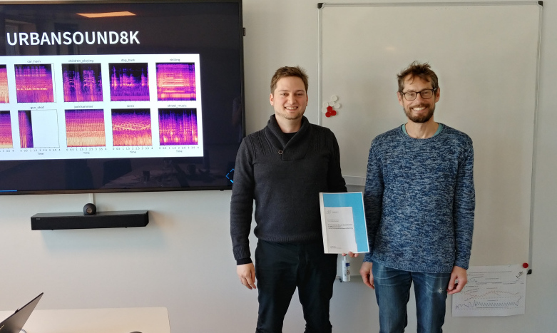
Master of Data Science thesis successfully defended. Left: me, Right: External sensor Lars Erik Solheim
Research
Throughout my degree, I’ve kept the vast majority of my notes in the open-source way – public on Github. Over time I have distilled these into two resources covering the main topics of my work.
Embedded Machine Learning: Machine Learning applied to Embedded System, with a focus on-edge ML in low-cost, low-power sensors.
Machine Hearing: Using Machine Learning on audio, with a focus on general sound (less music and speech).
Thesis
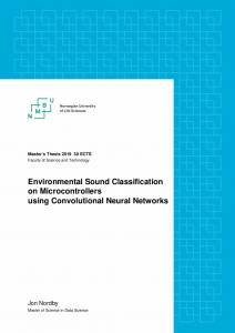
My masters thesis combined these two topics, and applied it to classification of everyday urban sounds for noise monitoring in smart cities. The report and all the code can be found on Github:
Since Embedded Machine Learning is an emerging niche, the availability of software tools are not as good as for machine learning in general. To help with that I developed emlearn, an open-source ML inference engine tailored for micro-controllers and very small embedded systems. emlearn allows to convert models built with existing Python machine learning frameworks such as scikit-learn and Keras, and execute them on device using portable C code. The focus is on simple and efficient models such as Random Forests, Decision Trees, Naive Bayes, linear models. In this way, emlearn is a compliment to deep learning inference libraries for embedded devices, such as TFLite and X-CUBE-AI.
Consulting
While the master degree was nominally a full time program, I kept doing engineering work for customers in the period. Projects have included:
dlock. A IoT doorlock system for retrofitting existing public infrastructure doors. Developed for municipality of Oslo as part of the Oslonøkkelen project, an app that allows inhabitants to access municipality services such as libraries and recycling stations outside of manned working-hours. Made in collaboration with IoT solutions provider Trygvis IO.
Since the start of this year, I have started to focus on machine learning projects. Especially things that incorporate my particular expertise: Embedded/Edge Machine Learning, Machine Learning for Audio, and Machine Learning on IoT sensor data. The first ML consulting project for Roest coffee is well underway (details to be announced). Going forward, most of my time is dedicated to products at my new startup, Soundsensing. However, there should also be some capacity for new consulting work.
Update: The dhang is now available for preorder, and you can join a workshop to build it yourself!
Feedback from first user testing of the dhang digital hand drum was that the latency was too high. How did we bring it down to a good level?
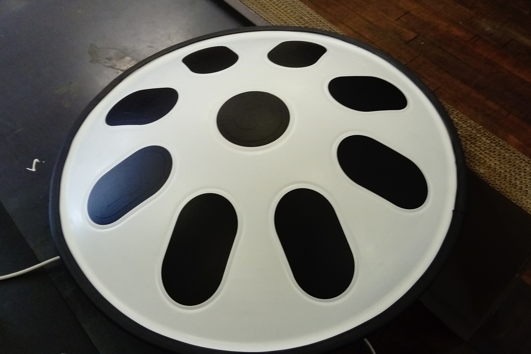
dhang: A MIDI controller using capacitive touch sensors for triggering. An Arduino board processes the sensor data and sends MIDI notes over USB to a PC or mobile device. A synthesizer on the computer turns the notes into sound.
Testing latency
For an interactive system like this, what matters is the performance experienced by the user. For a MIDI controller that means the end-to-end latency, from hitting the pad until the sound triggered is heard. So this is what we must be able to observe in order to evaluate current performance and the impact of attempted improvements. And to have concrete, objective data to go by, we need to measure it.
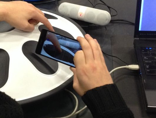
My first idea was to use a high-speed camera, using the video image to determine when pad is hit and the audio to detect when sound comes from the computer. However even at 120 FPS, which some modern cameras/smartphones can do, there is 8.33 ms per frame. So to find when pad was hit with higher accuracy (1ms) would require using multiple frames and interpolating the motion between them.
Instead we decided to go with a purely audio-based method:
Test setup for measuring MIDI controller end2end latency using audio recorded with smartphone.
The microphone is positioned close to the controller pad and the output speaker
The controller pad is tapped with the finger quickly and hard enough to be audible
Volume of the output was adjusted to be roughly same level as sound of physically hitting the pad
In case the images are useful for understanding the recorded test, video is also recorded
The synthesized sound was chosen to be easily distinguished from the thud of the controller pad
To get access to more settings, the open-source OpenCamera Android app was used. Setting a low video bitrate to save space, and enabling macro-mode for focusing close objects easier. For synthesizing sounds from the MIDI signals we use LMMS, a simple but powerful digital music studio.
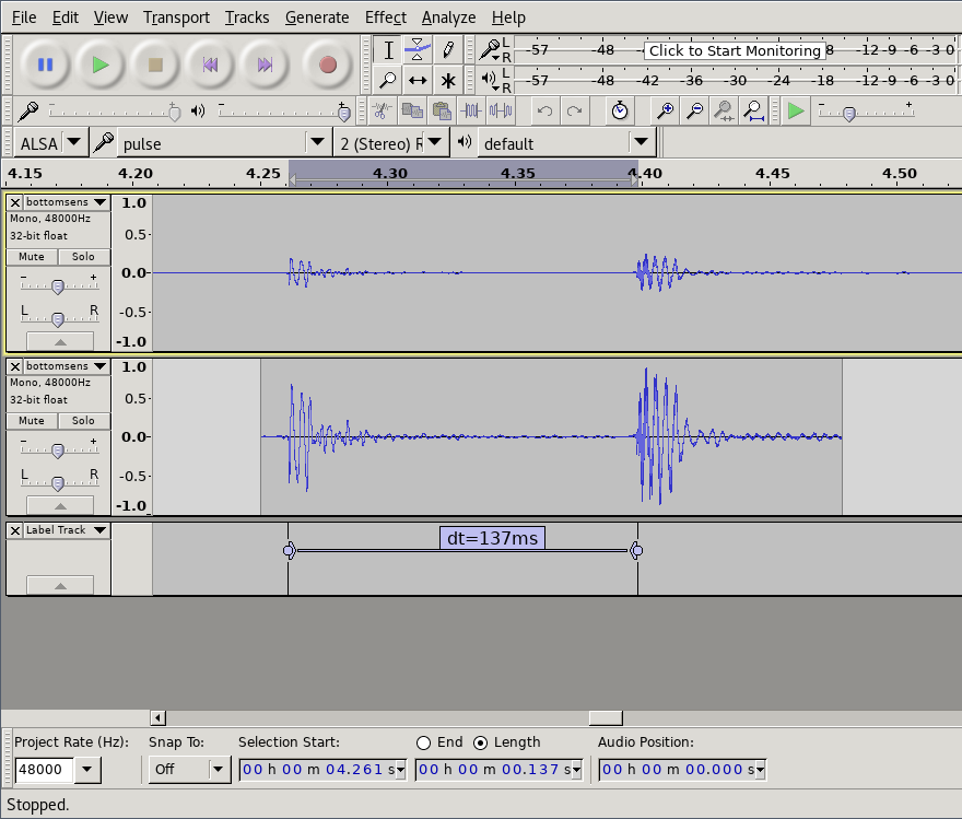
Then we open the video in Audacity audio editor to analyze the results. Using Effect->Amplify to normalize the audio to -1db makes it easier to see the waveforms. And then we can manually select and label the distance between the starting points of the sounds to get our end-to-end latency.
Raw sound data, data with normalized amplitude and measured distance between the sound of tapping the sensor and the sound coming from speakers.
How good is good enough?
We now know that the latency experienced by our testers was around 137 ms. For reference, when playing a (relatively slow) 4/4 beat at 120 beats per minute, the distance between each 16th notes is 125 ms. In the following soundclip the kickdrum is playing 4/4 and the ‘ping’ all 16 16th notes.
So the latency experienced would offset the sound by more than one 16th note! We can understand that this would make it tricky to play.
Wessel and Wright suggested that digital musical
instruments should aim for latency less than 10ms [22]
Dahl and Bresin [3] found that in a system
with latency, musicians execute their gestures ahead of the
beat to align the sound with a metronome, and that they
can maintain synchronisation this way up to 55ms latency.
Since the instrument in question is going to be a kit targeted at hobbyists/amateurs, we decided on an initial target of <30ms.
Sources of latency
Latency, like other performance issues, is a compounding problem: Each operation in the chain adds to it. However usually a large portion of the time is spent in a small parts of the system, so an important part of optimization is to locate the areas which matter (or rule out areas that don’t).
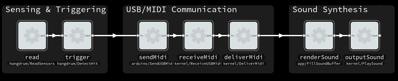
For the MIDI controller system in question, a software-centric view looks something like:
A functional view of the system and major components that may contribute to latency. Made with Flowhub
There are also sources of latency outside the software and electronics of the system. The capacitive effect that the sensor relies on will have a non-zero response time, and it takes time for sound played by the speakers to reach our ears. The latter can quickly be come significant; at 4 meters the delay is already over 10 milliseconds.
And at this time, we know what the total latency is, but don’t have information about how it is divided.
With simulation-hardened Arduino firmware
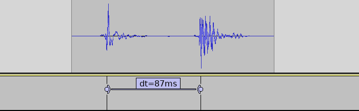
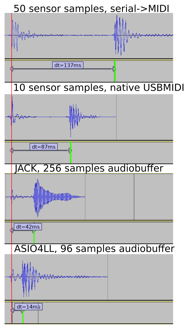
The system tested by users was running the very first hardware and firmware version. It used a an Arduino Uno. Because the Uno lacks native USB, a serial->MIDI bridge process had to run on the PC. Afterwards we developed a new firmware, guided by recorded sensor data and host-based simulation. From the data gathered we also decided to switch to a more sensitive sensor setup. And we switched to Arduino Leonardo with native USB-MIDI.
Latency with new firmware (with 1 sensor) was reduced by 50 ms (35%).
This firmware also logs how long each sensor reading cycle takes. It was under 1 ms for the recorded single-sensor setup. The sensor readings went almost instantly from low to high (1-3 cycles). So if the sensor reading and triggering takes just 3 ms, the remaining 84 ms must be elsewhere in the system!
Low-latency audio, a hard real-time problem
The two other main areas of the system are: the USB/MIDI communication from the Arduino to the PC, and the sound synthesis/playback. USB MIDI should generally be relatively low-latency, and it is a subsystem which we cannot influence so easily – so we focus first on the sound aspects.
Since a PC must be able to do multi-tasking, audio is processed in chunks: a buffer of N samples. This allows some flexibility. However if processing is interruptedfor toolong or too often, the buffer may not be completely filled. The resulting glitch is usually heard as a pop or crackle. The lower latency we want, the smaller the buffer, and the higher chance that something will interrupt for too long. At 96 samples/buffer of 48kHz samplerate, each buffer is just 2 milliseconds long.
With JACK on on Linux
I did the next tests on Linux, since I know it better than Windows. Configuring JACK to 256 samples/buffer, we see that the audio configuration does indeed have a large impact.
Latency reduced to half by configuring Linux with JACK for low-latency audio.
With ASIO4ALL on Windows
But users of the kit are unlikely to use Linux, so a solution that works with Windows is needed (at least). We tried all the different driver options in LMMS, switching to Hydrogen drum machine, as well as attempting to use JACK on Windows. None of these options worked well.
So in the end we tried going with ASIO, using the ASIO4LL replacement drivers. Since ASIO is proprietary LMMS/PortAudio does not support it out-of-the-box. Instead you have to manually replace the PortAudio DLL that comes with LMMS with a custom one 🙁 *nasty*.
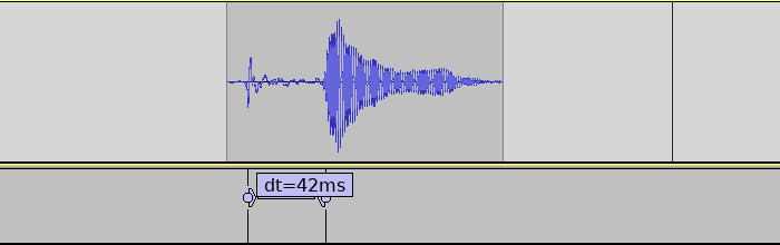
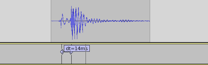
With ASIO4ALL we were able to set the buffer size as low as 96 samples, 2 buffers without glitches.
ASIO on Windows achieves very low latencies. Measurement of single sensor.
Completed system
Bringing back the 8 other sensors again adds around 6 ms to the sensor reading, bringing the final latency to around 20ms. There are likely still possibilities for significant improvements, but the target was reached so this will be good enough for now.
A note on jitter
The variation in latency of a audio system is called jitter. Ideally a musical instrument would have a constant latency (no jitter). When a musical instrument has significant amounts of jitter, it will be harder for the player to compensate for the latency.
Measuring the amount of jitter would require some automated tools for the audio analysis, but should otherwise be doable with the same test setup.
The audio pipeline should have practically no variation, but the USB/MIDI communication might be a source of variation. The CapacitiveSensor Arduino library is known to have variation in sensor readout time, depending on the current capacitance of the sensor.
Conclusions
By recording audible taps of the sensor with a smartphone, and analyzing with a standard audio editor, one can measure end-to-end latency in a tactile-to-sound instrument. A combination of tweaking the sensor hardware layout, improving the Arduino firmware, and configuring PC software for low-latency audio was needed to aceive acceptable levels of latency. The first round of improvements brought the latency down from an ‘almost unplayable’ 134 ms to a ‘hobby-friendly’ 20 ms.
Comparison of latency betwen the different configurations tested.
Last weekend at FOSDEM I presented in the Internet of Things (IoT) devroom,
showing how one can use MsgFlo with Flowhub to visually live-program devices that talk MQTT.
Since announcing MsgFlo in 2015, it has mostly been used to build scalable backend systems (“cloud”), using AMQP and RabbitMQ. At The Grid we’ve been processing hundred thousands of jobs each week, so that usecase is pretty well tested by now.
However, MsgFlo was designed from the beginning to support multiple messaging systems (including MQTT), as well as other kinds of distributed systems – like a networks of embedded devices working together (one aspect of “IoT”). And in MsgFlo 0.10 this is starting to work pretty nicely.
Visual system architecture
Typical MQTT devices have the topic names hidden in code. Any documentation is typically kept in sync (or not…) by hand.
MsgFlo lets you represent your devices and services as FBP/dataflow “components”, and a system as a connected graph of component instances. Each device periodically sends a discovery message to the broker. This message describing the role name, as well as what ports exists (including the MQTT topic name). This leads to a system architecture which can be visualized easily:
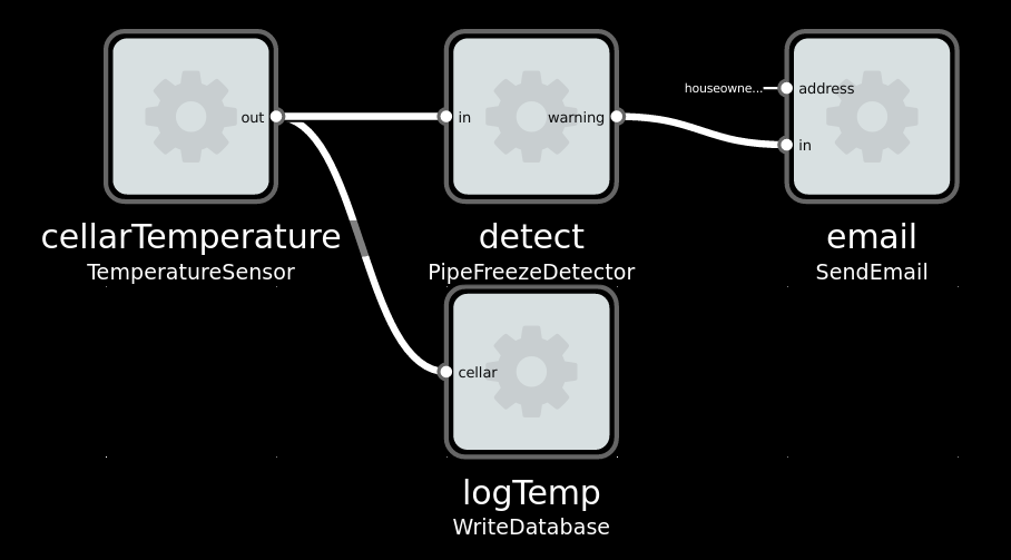
Imaginary solution to a typically Norwegian problem: Avoiding your waterpipes freezing in the winter.
Rewire live system
In most MQTT devices, output is sent directly to the input of another device, by using the same MQTT topic name. This hardcodes the system functionality, reducing encapsulation and reusability.
MsgFlo each device *should* send output and receive inports on topic namespaced to the device.
Connections between devices are handled on the layer above, by the broker/router binding different topics together. With Flowhub, one can change these connections while the system is running.
Change program values on the fly
Changing a parameter or configuration of an embedded device usually requires changing the code and flashing it. This means recompiling and usually being connected to the device over USB. This makes the iteration cycle pretty slow and tedious.
In MsgFlo, devices can (and should!) expose their parameters on MQTT and declare them as inports.
Then they can be changed in Flowhub, the device instantly reflecting the new values.
Great for exploratory coding; quickly trying out different values to find the right one.
Examples are when tweaking animations or game mechanics, as it is near impossible to know up front what feels right.
Add component as adapters
MsgFlo encourages devices to be fairly stupid, focused on a single generally-useful task like providing sensor data, or a way to cause actions in the real world. This lets us define “applications” without touching the individual devices, and adapt the behavior of the system over time.
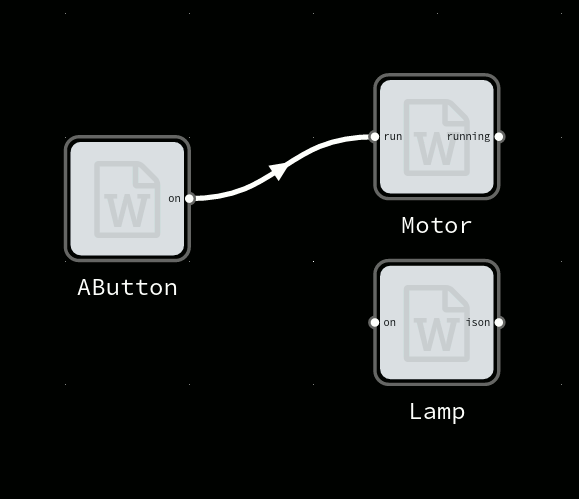
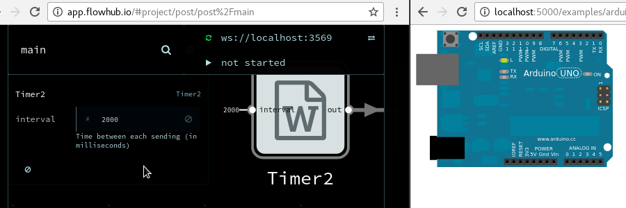
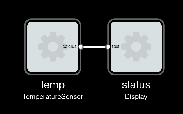
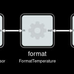
Imagine we have a device which periodically sends current temperature, as a floating-point number in Celcius unit. And a display device which can display text (for instance a small OLED). To show current temperature, we could wire them directly:
Our display would show something like “22.3333333”. Not very friendly, how does one know what this number means?
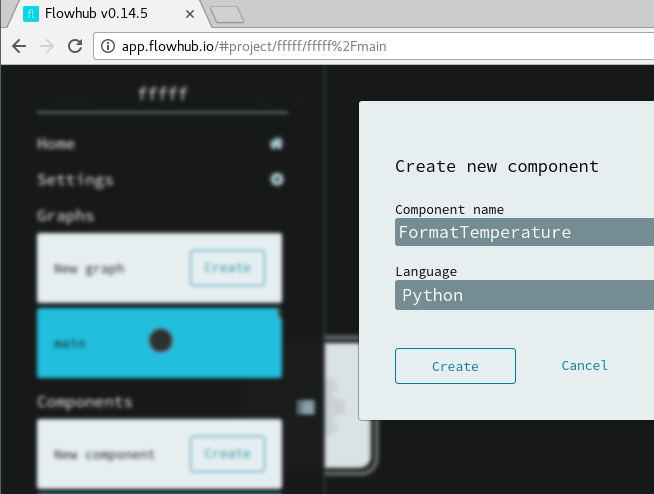
Better add a component to do some formatting.
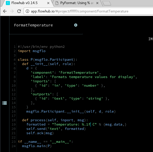
Adding a Python component
Component formatting incoming temperature number to a friendly text string
And then insert it before the display. This will create a new process, and route the data through it.
Our display would now show “Temperature: 22.3 C”
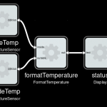
Over time maybe the system grows further
Added another sensor, output now like “Inside 22.2 C Outside: -5.5 C”.
Getting started with MsgFlo
If you have existing “things” that support MQTT, you can start using MsgFlo by either:
1) Modifying the code to also send the discovery message.
2) Use the msgflo-foreign-participant tool to provide discovery without code changes
If you have new things, using one of the MsgFlo libraries is a quick way to support MQTT and MsgFlo. Right now there are libraries for Python, C++11, Node.js, NoFlo and Arduino.
SuperCollider is an open source project for real-time audio synthesis and algorithmic composition.
It is split into two parts; an interpreter (sclang) implementing the SuperCollider language and the audio synthesis server (scsynth).
The server has an directed acyclic graph of nodes which it executes to produce the audio output (paper|book on internals). It is essentially a dataflow runtime, specialized for the problem domain of real-time audio processing. The client controls the server through OSC messages which manipulates this graph. Typically the client is some SuperCollider code in the sclang interpreter, but one can also use Clojure,Python or other clients. It is in many ways quite similar to the Flowhub visual IDE (a FBP protocol client) and runtimes like NoFlo, imgflo and MicroFlo.
So we decided to make SuperCollider a runtime too: sndflo.
Growing list of runtimes that Flowhub can target
We used SuperCollider for Piksels & Lines Orchestra, a audio performance system which hooked into graphics applications like GIMP, Inkscape, MyPaint, Scribus – and sonified the users actions in the application. A lot of time was spent wrestling with SuperCollider, due to the number of new concepts and myriad of ways to do things, and
lack of (well documented) best practices.
There is also a tendency to favor very short, expressive constructs (often opaque). An extreme example, here is an album of SuperCollider pieces composed with <140 characters (+ an analysis of some of them).
On the contrary sndflo is very focused and opinionated. It exposes Synths as components, which are be wired together using Busses (edges in the graph), allowing to build audio effect pipelines. There are several known issues and limitations, but it has now reached a minimally useful state. Creating Synths components (the individual effects) as a visual graph of UGen (primitives like Sin,Cos,Min,Max,LowPass) components is also within scope and planned for next release.
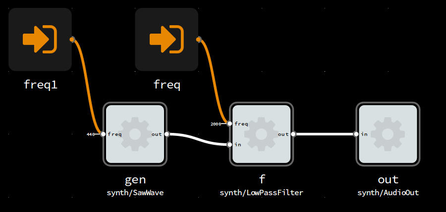
Simple substrative audio synthesis using sawwave and low-pass filter
The sndflo runtime is itself written in SuperCollider, as an extension. This is to make it easier for those familiar with SuperCollider to understand the code, and to facilitate integration with existing SuperCollider code and tools. For instance setting up a audio pipeline visually using Flowhub+sndflo, then using the Event/Pattern/Stream system in SuperCollider to create an algorithmic composition that drives this pipeline.
Because a web browser cannot talk OSC (UDP/TCP) and SuperCollider does not talk WebSocket a node.js wrapper converts messages on the FBP protocol between JSON over WebSocket to JSON over OSC.
sndflo also implements the remote runtime part of the FBP protocol, which allows seamless interconnection between runtimes. One can export ports in one runtime, and then use it as a component in another runtime, communicating over one of the supported transports (typically JSON over WebSocket).
In above example sndflo runs on a Raspberry Pi, and is then used as a component in a NoFlo browser runtime to providing a web interface, both programmed with Flowhub. We could in the same way wire up another FBP runtime, for instance use MicroFlo on Arduino to integrate some physical sensors into the system.
Pretty handy for embedded systems, interactive art installations, internet-of-things or other heterogenous systems.
Lately I’ve been playing with microcontrollers again; Atmel AVRs with and without Arduino boards. I’ve make a couple of tiny projects myself, helped an artist friend do interactive works and helped to integrated a microcontroller it in an embedded product at work. With Arduino, one does not have to worry about interrupts, registers and custom hardware programmers to get things done using a microcontroller. This has opened the door for many more people that pre-Arduino. But the Arduino language is just a collection of C++ classes and functions, users are still left with telling the microcontroller how to do things; “first do this, then this, then this…”.
I think always having to work on such a a low level limits what people make with Arduino, both in who’s able to use it and what current users are able to achive. So, I created a new experimental project: MicroFlo. It has a couple of goals, the two first being the most important:
People should not need to understand text-based, C style programming to be able to program microcontrollers. But those that do know it should be able to use that knowledge, and be able to mix-and-match it with higher-level paradims within a single program.
It should be possible to verify correctness of a microcontroller program in an automated way, and ideally in a hardware-independent manner.
Inspired by NoFlo, and designed for integration with it, MicroFlo implements Flow-based programming (FBP). In FBP, a program is constructed by connecting a set of independent components. Each component has in-ports and out-ports, and can only communicate with eachother through these. The connections can be defined using programatically, using a declarative text language, or using a visual editor. 2D/3D artists will recognise this the concept from node compositors like in Blender, sound artists from applications like Reaktor.
Current status: A fridge
I have an old used fridge, by the looks of it made in the GDR some time before I was born. Not long after I got it, the thermostat broke and the cooler would not turn off. Instead of throwing it away and getting a new one, which would be the cool and practical* thing to do, I decided to fix it. Using an Arduino and MicroFlo.
* especially considering that it is several months since it broke…
A fridge is a simple system, something that should be simple for hobbyists to create. So it was a decent first usecase to test the framework on. Principially, such a system looks something like this:
The thermostat decides whether to turn the cooler on or off, and the cooler switch realizes this decision. There are many alternative methods of implemening each of these two components. I used a DS1820 digital thermometer IC to read temperature, and a hacked NEXA remote controlled relay for the switch.
All the logic, including temperature threshold is done in software on an Arduino Uno.
The code below for the cooler switch would have been simpler (a oneliner, left as excersise for the reader) if I instead had used a active high relay directly on the mains (illegal if not a certified electrician). Or alternatively reverse-engineered the 433Mhz protocol used.
MicroFlo code for the fridge, in the .FBP domain specific language (examples/fridge.fbp) # Thermostat
timer(Timer) OUT -> TRIGGER thermometer(ReadDallasTemperature)
thermometer() OUT -> IN hysteresis(HysteresisLatch)
# On/Off switch
hysteresis() OUT -> IN switch(BreakBeforeMake)
switch() OUT1 -> IN ia(InvertBoolean) OUT -> IN turnOn(DigitalWrite)
switch() OUT2 -> IN ic(InvertBoolean) OUT -> IN turnOff(DigitalWrite)
# Feedback cycle to switch required for syncronizing break-before-make logic
turnOn() OUT -> IN ib(InvertBoolean) OUT -> MONITOR1 switch()
turnOff() OUT -> IN id(InvertBoolean) OUT -> MONITOR2 switch()
Is the above solution nicer than using the Arduino IDE and writing in C++? At the moment maybe not significantly so. But it does prove that this kind of high-level dynamic programming model is feasible to implement also on devices with 2kB RAM and 32kB program memory. And it is a starting point for more interesting exploration.
Next steps
I will continue to experiment with using MicroFlo for new projects, to develop more components and test/validate the architecture and programming model. I also need to read through all of the canonical book on FBP by J. Paul Morrison.
Some bigger things that I want to add include:
Ability to introspect the graph running on the device, in particular the packets moving between components.
Automated testing (of the framework, individual components and application graphs) using JavaScript BDD test frameworks like Mocha or Vows.
Ability to change graphs at runtime, and then persist it to EEPROM so it will be loaded on next reset.
And eventually: Allowing to manipulate and monitor running graphs visually, using the NoFlo development environment. See bug #1.