Lately I’ve been playing with microcontrollers again; Atmel AVRs with and without Arduino boards. I’ve make a couple of tiny projects myself, helped an artist friend do interactive works and helped to integrated a microcontroller it in an embedded product at work. With Arduino, one does not have to worry about interrupts, registers and custom hardware programmers to get things done using a microcontroller. This has opened the door for many more people that pre-Arduino. But the Arduino language is just a collection of C++ classes and functions, users are still left with telling the microcontroller how to do things; “first do this, then this, then this…”.
I think always having to work on such a a low level limits what people make with Arduino, both in who’s able to use it and what current users are able to achive. So, I created a new experimental project: MicroFlo. It has a couple of goals, the two first being the most important:
People should not need to understand text-based, C style programming to be able to program microcontrollers. But those that do know it should be able to use that knowledge, and be able to mix-and-match it with higher-level paradims within a single program.
It should be possible to verify correctness of a microcontroller program in an automated way, and ideally in a hardware-independent manner.
Inspired by NoFlo, and designed for integration with it, MicroFlo implements Flow-based programming (FBP). In FBP, a program is constructed by connecting a set of independent components. Each component has in-ports and out-ports, and can only communicate with eachother through these. The connections can be defined using programatically, using a declarative text language, or using a visual editor. 2D/3D artists will recognise this the concept from node compositors like in Blender, sound artists from applications like Reaktor.
Current status: A fridge
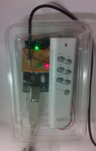
I have an old used fridge, by the looks of it made in the GDR some time before I was born. Not long after I got it, the thermostat broke and the cooler would not turn off. Instead of throwing it away and getting a new one, which would be the cool and practical* thing to do, I decided to fix it. Using an Arduino and MicroFlo.
* especially considering that it is several months since it broke…
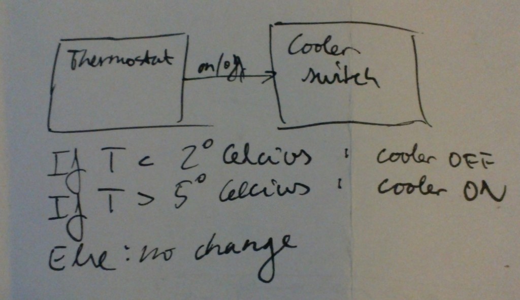
A fridge is a simple system, something that should be simple for hobbyists to create. So it was a decent first usecase to test the framework on. Principially, such a system looks something like this:
The the rmostat decides whether to turn the cooler on or off, and the cooler switch realizes this decision. There are many alternative methods of implemening each of these two components. I used a DS1820 digital thermometer IC to read temperature, and a hacked NEXA remote controlled relay for the switch.
All the logic, including temperature threshold is done in software on an Arduino Uno.
The code below for the cooler switch would have been simpler (a oneliner, left as excersise for the reader) if I instead had used a active high relay directly on the mains (illegal if not a certified electrician). Or alternatively reverse-engineered the 433Mhz protocol used.
MicroFlo code for the fridge, in the .FBP domain specific language (examples/fridge.fbp)
# Thermostat

timer(Timer) OUT -> TRIGGER thermometer(ReadDallasTemperature)

thermometer() OUT -> IN hysteresis(HysteresisLatch)
# On/Off switch
hysteresis() OUT -> IN switch(BreakBeforeMake)
switch() OUT1 -> IN ia(InvertBoolean) OUT -> IN turnOn(DigitalWrite)
switch() OUT2 -> IN ic(InvertBoolean) OUT -> IN turnOff(DigitalWrite)
# Feedback cycle to switch required for syncronizing break-before-make logic
turnOn() OUT -> IN ib(InvertBoolean) OUT -> MONITOR1 switch()
turnOff() OUT -> IN id(InvertBoolean) OUT -> MONITOR2 switch()
# Config
‘5000’ -> INTERVAL timer() # milliseconds
‘2’ -> LOWTHRESHOLD hysteresis() # Celcius
‘5’ -> HIGHTHRESHOLD hysteresis() # Celcius
‘[“0x28”, “0xAF”, “0x1C”, “0xB2”, “0x04”, “0x00”, “0x00”, “0x33”]’ -> ADDRESS thermometer()
board(ArduinoUno) PIN9 -> PIN thermometer()
board() PIN12 -> PIN turnOff()
board() PIN11 -> PIN turnOn()
Next steps
I will continue to experiment with using MicroFlo for new projects, to develop more components and test/validate the architecture and programming model. I also need to read through all of the canonical book on FBP by J. Paul Morrison.
Some bigger things that I want to add include:
- Ability to introspect the graph running on the device, in particular the packets moving between components.
- Automated testing (of the framework, individual components and application graphs) using JavaScript BDD test frameworks like Mocha or Vows.
- Ability to change graphs at runtime, and then persist it to EEPROM so it will be loaded on next reset.
And eventually: Allowing to manipulate and monitor running graphs visually, using the NoFlo development environment. See bug #1.
Curious still? Check out the code, and ask on the FBP mailing list if you have any questions!
